Dwyer PFT-IAN-B111-S Paddlewheel Flow Tracker
Posted on: 02/06/2026
In the operation of water-cooled central air conditioning networks, controlling flow parameters (GPM or m3/h) in chilled water and cooling water pipelines is a mandatory input requirement. This data enables the Building Management System (BMS) to accurately calculate the thermal energy (BTU) being consumed and issue variable frequency drive commands to secondary pumps. The PFT-IAN-B111-S flow velocity sensor by Dwyer, utilizing paddlewheel technology, perfectly addresses the need for real-time measurement with exceptionally low error margins.
What is the Dwyer PFT-IAN-B111-S Flow Tracker?
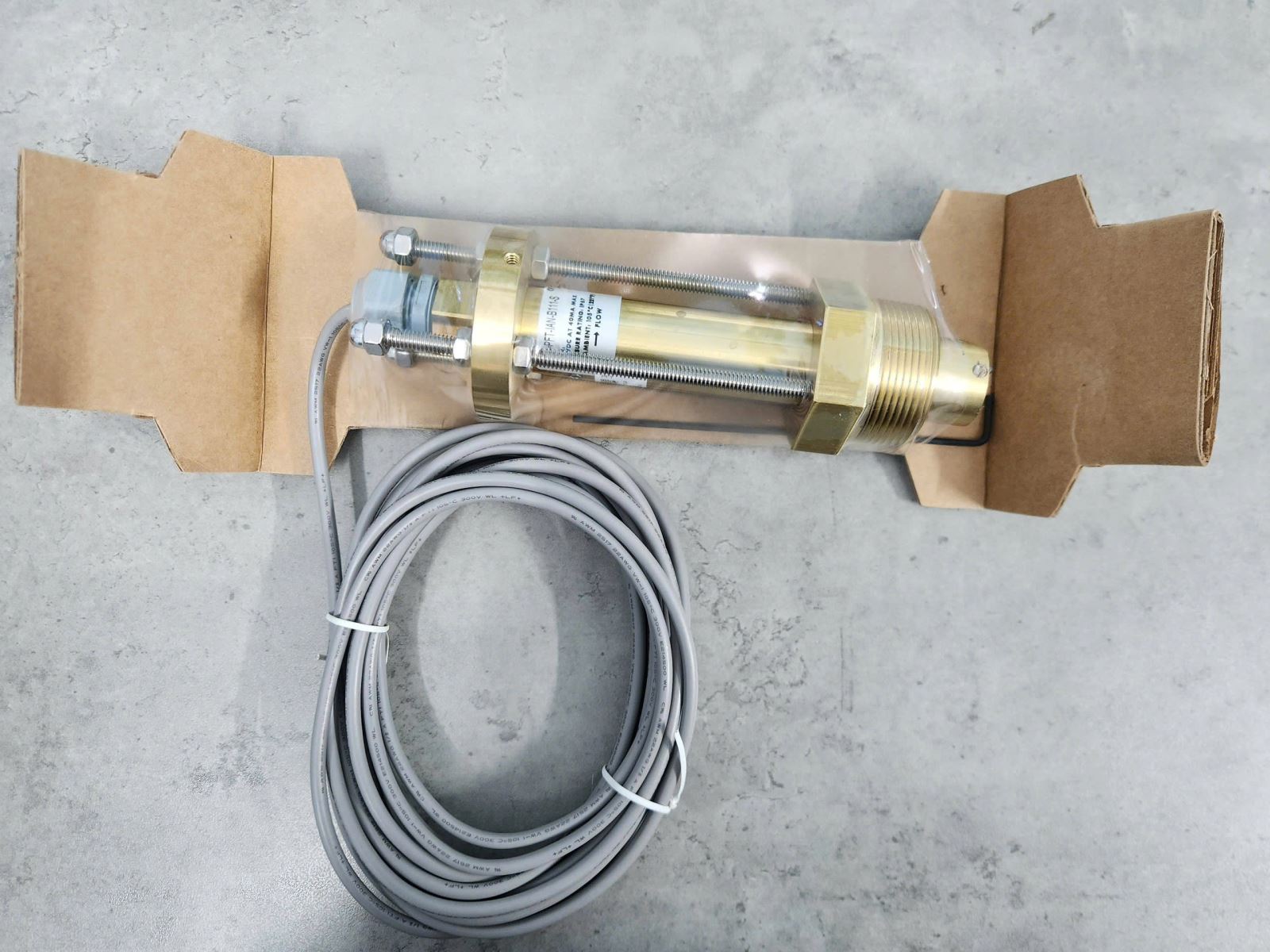
The PFT-IAN-B111-S model (part of the Paddlewheel Flow Tracker series) is an insertion-type flow sensor. It is designed to be inserted directly into the pipeline via a saddle or T-fitting, allowing it to measure the velocity of the liquid moving across the pipe's cross-section. Featuring a probe made of Brass combined with stainless steel, the device is highly resistant to corrosion from industrial media.
Structure and Key Advantages
-
Magnetic Pulse Counting Principle: The paddlewheel rotates as water flows past. Embedded magnets within the paddlewheel pass by a non-contact Hall-effect sensor, which counts the magnetic pulses and generates a linear square wave output.
-
Easy Maintenance: Thanks to its insertion design, engineers can easily extract the sensor assembly from the pipe to clean the paddlewheel without needing to cut or replace a whole section of pipe, unlike static inline magnetic meters.
-
Flexible Signal Output: Integrates pulse or Analog (4-20mA/0-10V) output options when paired with a converter, making it compatible with any existing DDC controller.
Straight Pipe Requirement
A common and severe mistake made by M&E installation engineers is placing the water velocity sensor too close to elbows (90-degree bends), tees, pumps, or control valve assemblies. In these locations, the flow experiences significant turbulence, creating water vortices and air bubbles. This causes the paddlewheel to spin irregularly and can send false signals with up to 20-30% deviation to the central BMS.
For the PFT-IAN-B111-S to achieve maximum accuracy, piping design codes mandate adhering to ideal installation distances: a minimum straight pipe run upstream of the sensor equal to 10 times the pipe diameter (10D), and a minimum straight pipe run downstream equal to 5 times the pipe diameter (5D). The most ideal location is a straight discharge section after the water exits the Chiller evaporator at a safe distance.
Safe Installation Guidelines
-
Depth Positioning: The probe depth must be adjusted so that the center of the paddlewheel sits at approximately 12% of the pipe diameter inward from the pipe wall. This position best represents the average flow velocity.
-
Horizontal Installation: The device should be installed on the side of the pipe (at the 3 o'clock or 9 o'clock position) rather than at the top (where air bubbles accumulate) or the bottom (where rust and scale gather and jam the paddlewheel).
Technical Specifications from PFT-IAN-B111-S Catalog
|
Technical Parameter
|
Details
|
|
Measurement Velocity Range
|
1.2 to 25 ft/s (0.37 to 7.62 m/s)
|
|
Accuracy
|
±1% over the entire range
|
|
Body Material
|
Brass - IAN standard
|
|
Paddlewheel Material
|
PVDF with high mechanical durability, scale-resistant
|
|
Maximum Working Pressure
|
400 psig (27.6 bar) @ 100°F (37.8°C)
|
|
Maximum Media Temperature
|
Up to 212°F (100°C)
|
|
Connection Cable
|
Specialized 3-core shielded cable
|
Consult on Water Measurement Equipment at DLK
DLK TRADING SERVICES CO., LTD is a professional supplier of Dwyer (USA) water flow, temperature, and pressure measurement devices. We offer comprehensive solutions ranging from equipment selection and straight pipe calculation to assisting in converting pulse signals into volumetric flow directly on the DDC system.