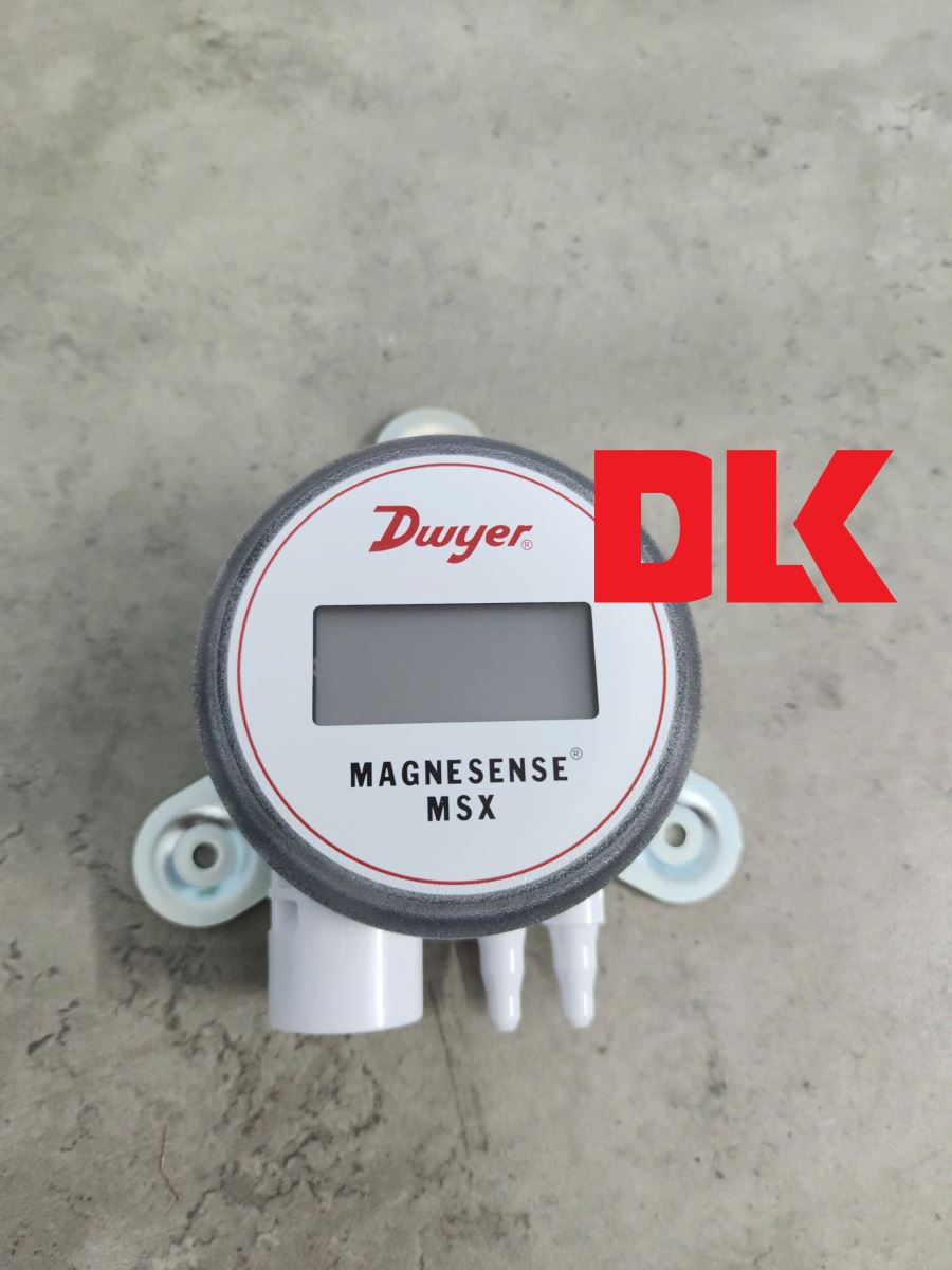
Calibration and Configuration Guide for Dwyer Magnesense® MSX-W10-PA-LCD
After completing the wiring process, calibration and range configuration are the final steps to ensure your MSX-W10-PA-LCD operates with peak precision. The integrated LCD model offers a significant advantage, allowing technicians to monitor real-time pressure and navigate settings menus with visual feedback.
1. Understanding the Control Interface
Under the protective cover of the MSX-W10-PA-LCD, you will find two primary digital push-buttons:
-
Zero Button: Used to reset the zero point (Zero Calibration) and to decrease values or move "down" in the programming menu.
-
Span Button: Used to set the maximum range (Span Calibration) and to increase values or move "up" in the menu.
Technical Note: There is a 3-second delay from the time you release the buttons until the calibration takes effect. This prevents stress-related offsets or vibration errors during manual handling.
2. Zero Calibration Procedure
Zeroing the transmitter is the most critical maintenance task. It should be performed after installation and periodically to eliminate static offsets.
-
Power the unit for at least 15 minutes to allow the sensor to reach thermal stability.
-
Disconnect all pressure tubing. Both the Positive (+) and Negative (-) ports must be vented to the atmosphere.
-
Press and hold the Zero button for 3 seconds.
-
The LCD will display ZERO. Once successful, it will return to the home screen showing 0.000 (or the equivalent in your selected unit).
3. Span Calibration Procedure
Only perform this step if you have a high-precision pressure source for reference.
-
Perform a Zero Calibration first (as described above).
-
Apply the exact maximum pressure (Full-scale) for your desired range to the Positive (+) port.
-
Press and hold the Span button for 3 seconds.
-
The LCD will display SPAN. The transmitter will now associate this applied pressure with the 100% analog output (20mA or 10V).
4. Range Selection via DIP Switches
The MSX-W10-PA-LCD features an 8-position DIP switch bank for rapid field configuration:
-
DIP 1 & 2 (Units): Select between Pa, mm w.c., or in w.c.
-
DIP 3 (Mode): Toggle between Pressure (OFF) or Velocity/Flow (ON).
-
DIP 4 (Output): Set Voltage output to 0-10V (OFF) or 0-5V (ON).
-
DIP 5 (Direction): Set to Unidirectional (OFF) or Bidirectional (ON).
-
DIP 7 & 8 (Max Range): Defines the upper limit of the output signal based on the factory range set.
5. Troubleshooting LCD Error Messages
If the system encounters an issue, the LCD will display one of the following diagnostic codes:
|
Error Code |
Meaning |
Recommended Action |
|
OVER |
Pressure is 3% higher than the selected max range. |
Check system pressure or increase the range via DIP 7&8. |
|
UNDR |
Pressure is 1% lower than the selected min range. |
Check for reversed tubing on (+) and (-) ports. |
|
FAIL |
Span pressure is out of range for calibration. |
Verify your reference pressure source is accurate and stable. |
|
ER 1 |
Pressure exceeds the sensor's physical limit. |
Remove pressure immediately to prevent sensor damage. |
|
ER 3 |
Internal sensor communication failure. |
Contact DLK technical support for warranty service. |
6. Expert Tips from DLK Service Center
DLK TRADING SERVICE CO., LTD – Authorized Dwyer distributor – provides the following expert recommendations:
-
Display Rotation: The LCD is 180° rotatable. If you must mount the transmitter with ports facing up (though not recommended), you can flip the display for easy reading.
-
Damping (Response Time): If the LCD reading is fluctuating due to air turbulence, toggle DIP 6 to the ON position. This adds a 3-second dampening filter to stabilize the output.
-
Security: You can set a 4-digit PIN code in the software menu to lock the buttons and prevent unauthorized calibration changes.
Mastering the calibration of the MSX-W10-PA-LCD ensures your ventilation and cleanroom systems maintain the strict pressure differentials required for safety and efficiency.